

 EN
 Español
 Indonesia
 Tiếng Việt


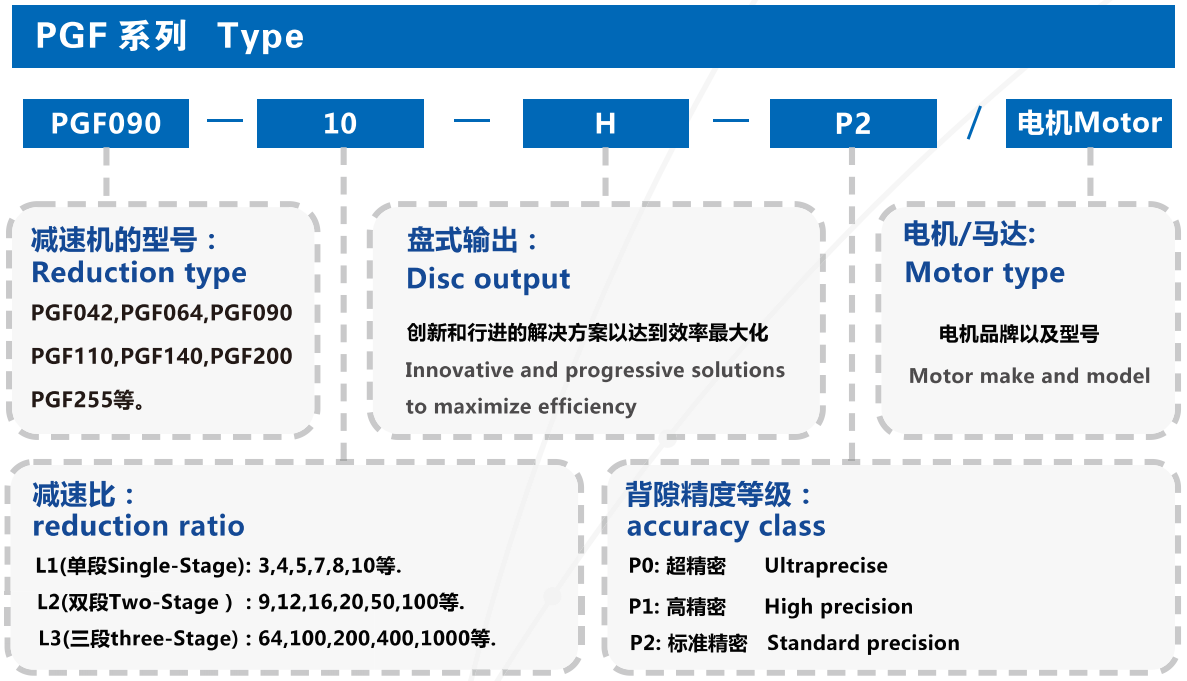
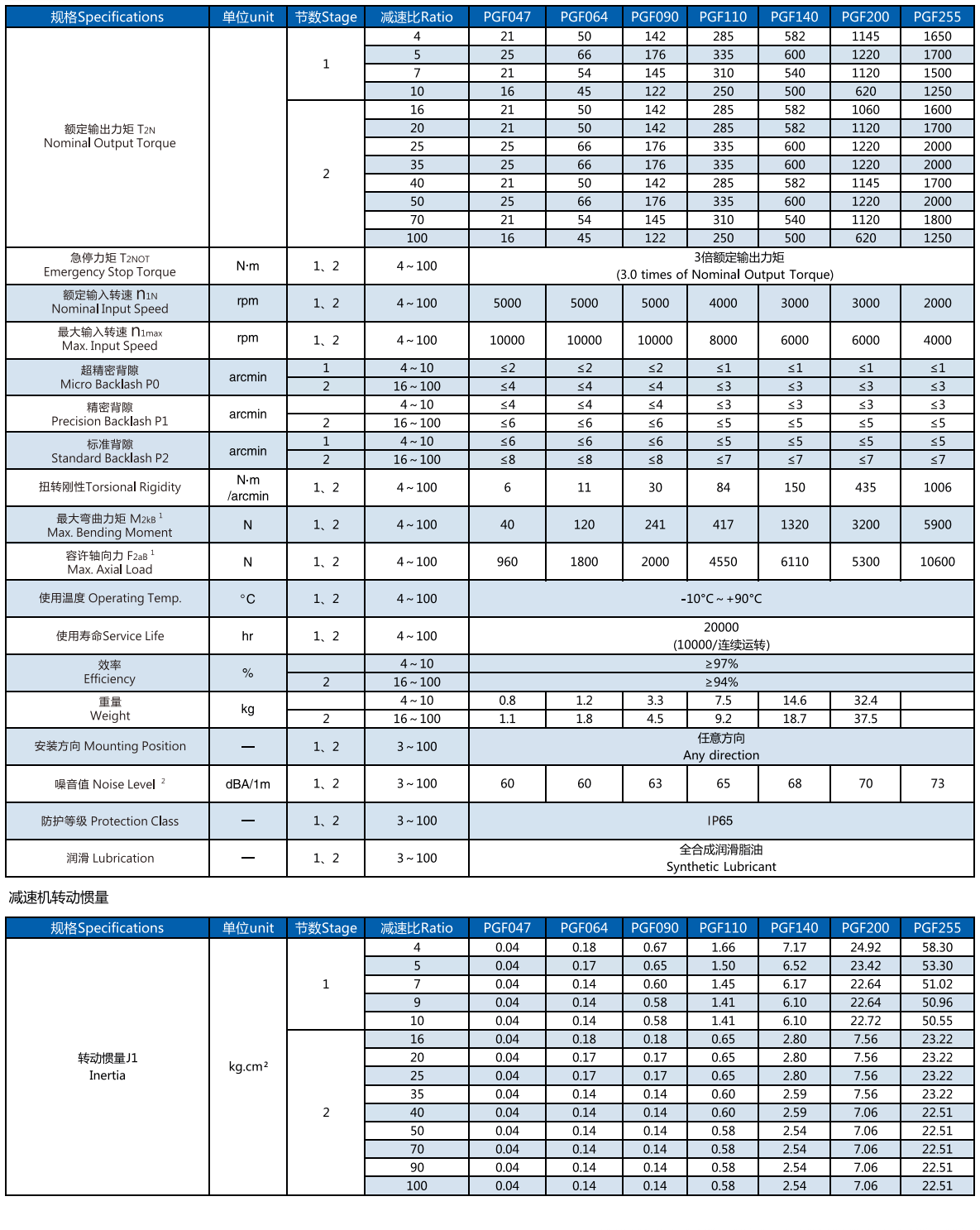
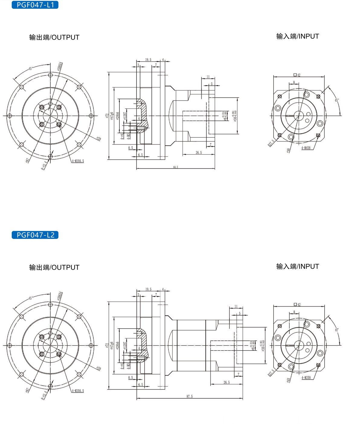
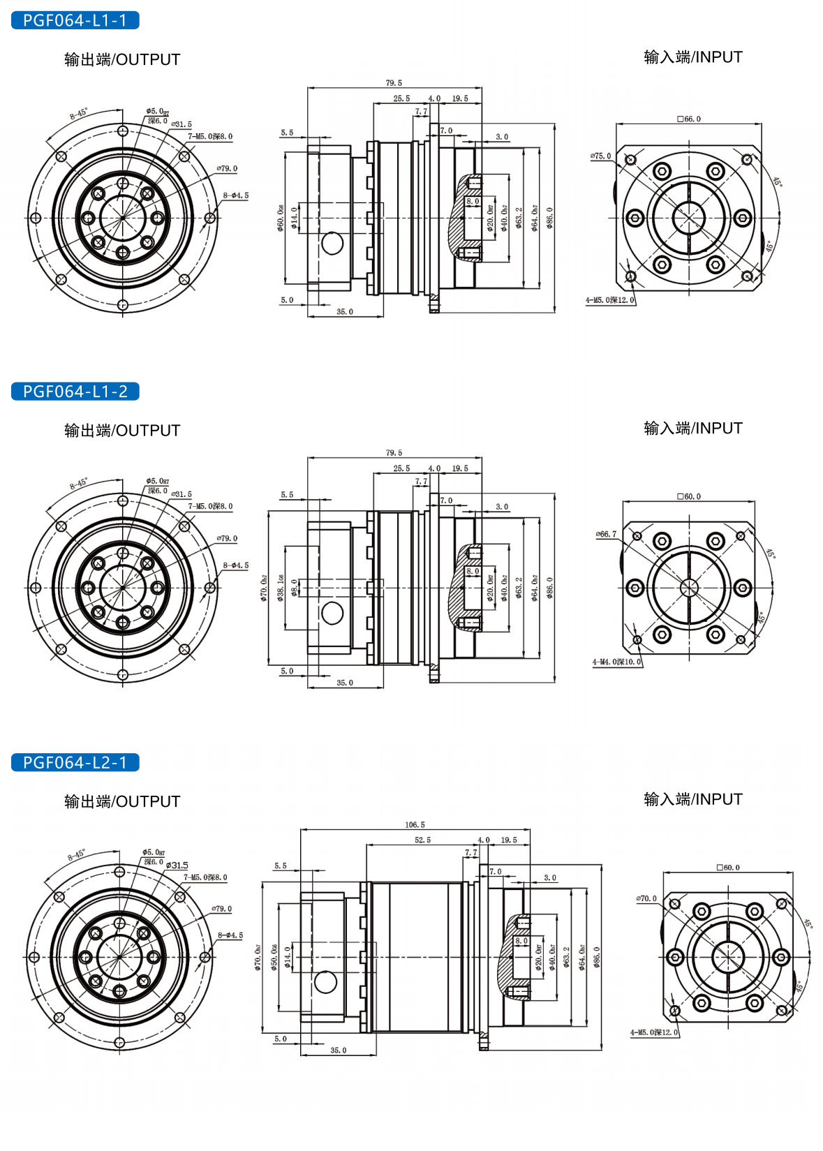
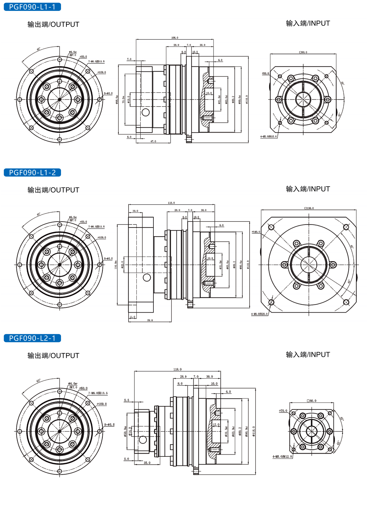
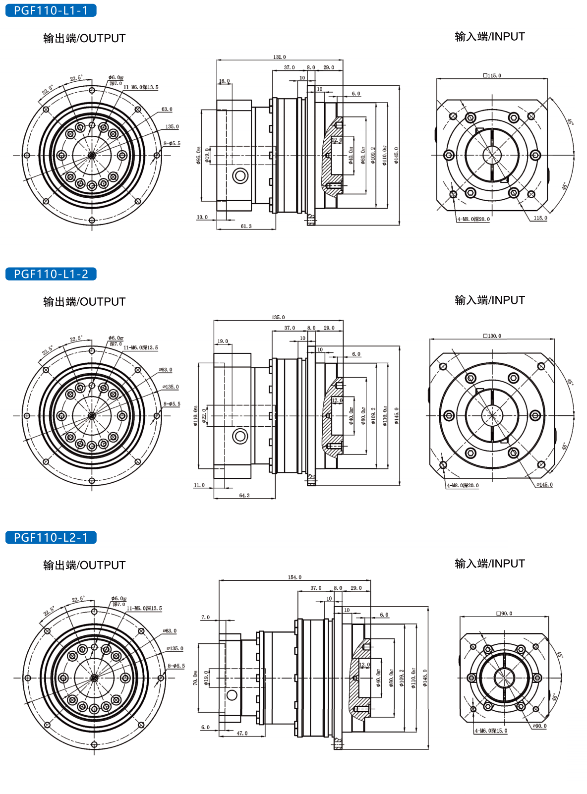
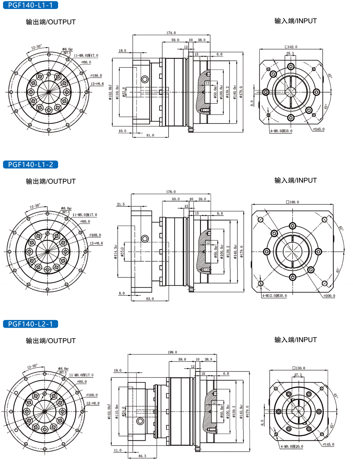
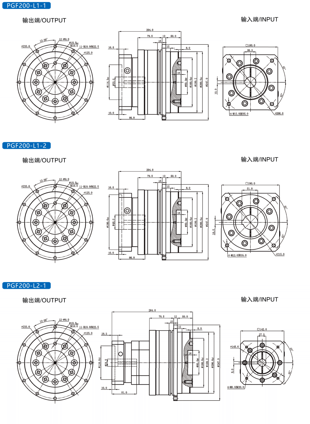
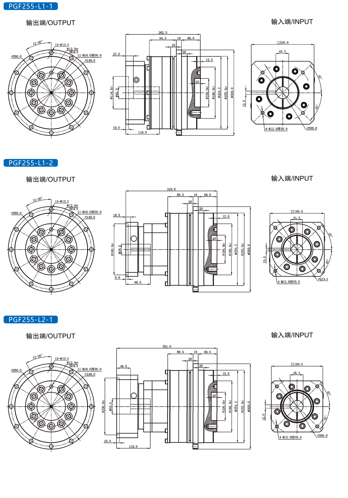
At HOAJEAR Intelligent Manufacturing (Suzhou) Co., Ltd., we design and manufacture planetary gearboxes for industrial drive systems. Our PGF High Precision Helical Gear Reducer is part of our approach to compact transmission, useful output torque and controlled movement. We help machine builders choose a configuration around the motor, driven mechanism and daily operating cycle.
We know that a gearbox purchase often starts with a short requirement: move this load, fit this space and stop at this position. We turn those requirements into checks that your engineering, purchasing and assembly teams can follow.
1. What We Look for in a Practical Precision Gear Reducer
We use a reducer when a motor's speed and torque need to be adapted to the machine. A motor may work comfortably at a relatively high speed while a table, roller or handling mechanism needs slower movement. We bring the speed down and increase the available output torque within the selected gearbox's limits.
With our PGF high precision helical gear reducer, we focus on the connection between that basic function and the required motion. A feed axis, rotary fixture and conveyor can all need reduction, but their loads, reversals and stopping requirements can differ considerably.
We consider the complete installation rather than the gearbox body alone. Motor connectors need space, fastening tools need access and the driven mechanism needs a suitable connection. We review those details early because a small interference can delay assembly even when the torque calculation is correct.
For flange-connected installations, we check the locating features, mounting face, fastening pattern and load support against the approved drawing. Where the connection uses another arrangement, we review its dimensions and method of transmitting torque. We confirm the actual PGF configuration before treating any interface as interchangeable.
We also ask how the machine will operate throughout a shift. Frequent starts, short moves and repeated direction changes need a different review from steady running. The weight being moved is useful information, but it does not describe the acceleration or the forces acting on the output connection.
Our starting point is the work the axis must complete. Please tell us the required speed, movement time, load position and stopping requirement. With that information, we can discuss a precision planetary gearbox for automation using details that relate to the machine itself.
2. How We Use Helical Gearing and Select the Reduction Ratio
We use a planetary arrangement to package reduction around a central drive axis. In a conventional arrangement, a sun gear works with surrounding planet gears and an internal ring gear. The way these parts are driven or held determines the resulting motion.
Helical teeth are angled, so their contact develops progressively across the tooth width. We use this form of engagement to support smooth transmission. We also account for the axial forces associated with helical contact. Bearing support, alignment and assembly remain important parts of the gearbox design.
We calculate output speed by dividing input speed by the total reduction ratio. To estimate transmitted output torque, we multiply input torque by ratio and efficiency, then check the selected gearbox rating. We never treat that multiplication as permission to exceed the mechanical limits.
| Example ratio | Assumed input speed | Calculated output speed | Calculated output torque |
|---|---|---|---|
| 5:1 | 2,500 rpm | 500 rpm | 6.75 N·m |
| 10:1 | 2,500 rpm | 250 rpm | 13.50 N·m |
| 20:1 | 2,500 rpm | 125 rpm | 27.00 N·m |
Source: our calculations using the speed and torque relationships in Oriental Motor's Gearhead Selection for Stepper Motors. We assume 1.5 N·m input torque and 90% transmission efficiency. These figures are selection examples, not PGF test results, available ratio confirmation or rated capacities.
We use a comparison like this to discuss the speed and torque balance. A larger ratio may provide more output torque from the assumed input, but the output also turns more slowly. We still need the axis to complete its movement within the available cycle time.
We also explain that reduction changes the balance between speed and torque; it does not create power. Some input power is lost through friction and other effects. We therefore check the motor's available power together with the required motion, especially when customers ask for more output torque while keeping the same speed and motor.
We check efficiency for the selected operating condition rather than applying one percentage everywhere. Speed, load and temperature can affect losses. If the machine spends much of its time running lightly loaded or repeatedly accelerating, we review that duty separately from a steady operating point.
For noise requirements, we agree on the measuring distance and operating conditions. We consider the motor, mounting structure and connected mechanism because the sound heard beside a machine comes from the complete assembly.
3. Why We Check Inertia Alongside Torque
We describe inertia as resistance to a change in rotational speed. A large rotary fixture can require substantial effort to accelerate even if it turns freely once moving. That is why we ask about fixture dimensions and load position alongside weight.
We use the reduction ratio to understand the load seen from the motor. For the external load contribution, reflected inertia equals output-side load inertia divided by the square of the ratio. We then include the gearbox's own input inertia and any other rotating parts in the complete assessment.
| Example ratio | Assumed output-side load inertia | Calculated reflected load inertia | External load contribution to inertia ratio |
|---|---|---|---|
| 5:1 | 0.0400 kg·m² | 0.0016 kg·m² | 8:1 |
| 10:1 | 0.0400 kg·m² | 0.0004 kg·m² | 2:1 |
| 20:1 | 0.0400 kg·m² | 0.0001 kg·m² | 0.5:1 |
Source: our calculations using the reflected-inertia relationship explained in Oriental Motor's Motor Sizing Basics Part 2: How to Calculate Load Inertia. We assume motor rotor inertia of 0.0002 kg·m². Gearbox inertia and other input-side components are excluded. These are examples, not motor acceptance limits or PGF specifications.
We use these results to compare possible drive arrangements. We still check the output speed, motor acceleration and gearbox loading. A smaller reflected load contribution can be useful, but it does not prove that the complete axis will settle within the required time.
For repeated motion, we ask for the cycle in stages: acceleration, travel, deceleration and pause. We also ask whether the carried load changes. An empty return movement may place different demands on the motor from a loaded outward movement.
We review the motor's continuous and peak torque at the intended speed. The highest torque printed on a motor sheet may only apply for a limited period. We compare the proposed cycle with the applicable motor and gearbox limits before recommending the combination.
For external loads, we ask whether the mechanism has its own bearings. A gearbox driving a supported shaft faces a different installation from one carrying an overhung pulley. We need the force location as well as its size. This helps us assess the connection and discuss whether additional support belongs in the machine design.
When control behaviour matters, we discuss the mechanical arrangement with the customer's controls team. Mounting stiffness, feedback location and tuning all influence the movement that the machine finally delivers.
4. How We Relate Backlash to Positioning Requirements
We describe backlash as angular clearance that can become apparent when the drive reverses. For a PGF precision helical gearbox used on a positioning axis, we want to know whether the mechanism approaches its target from one direction or alternates between directions.
We make angular clearance easier to picture by converting it into travel at a chosen radius. One arcminute equals one sixtieth of a degree. The farther the working point sits from the rotation centre, the greater the travel associated with the same angle.
| Example angular clearance | Travel at 50 mm radius | Travel at 100 mm radius | Travel at 150 mm radius |
|---|---|---|---|
| 2 arcmin | 0.0291 mm | 0.0582 mm | 0.0873 mm |
| 4 arcmin | 0.0582 mm | 0.1164 mm | 0.1745 mm |
| 6 arcmin | 0.0873 mm | 0.1745 mm | 0.2618 mm |
Source: our geometric calculations using arc travel s = r × θ, with θ = arcmin × π / 10,800 radians. Values are rounded. The angles are comparison inputs, not available PGF accuracy grades or measured machine errors.
We treat this conversion as one part of the positioning review. A coupling can move, a mounting plate can bend and a shaft can twist under load. We need to consider these effects when discussing the movement measured at the actual tool, gripper or workpiece.
We also distinguish backlash from stiffness. Backlash concerns clearance during reversal. Torsional stiffness describes resistance to twisting under torque. A mechanism can meet its clearance requirement yet still deflect while applying force, so we review the working load as well as the unloaded position.
For acceptance, we recommend agreeing on load, approach direction, temperature condition and measuring location. We also separate repeatability from absolute accuracy: returning consistently to one point and reaching the commanded point accurately are related but different requirements.
When customers request a low backlash planetary gearbox for servo positioning, we ask for the required result in practical terms. A target at the gearbox output and a target at the end of a long arm need different reviews.
5. Where We Apply the PGF Reducer in Industrial Machinery
Packaging and converting equipment
We consider the PGF reducer for suitable feed, indexing and transfer mechanisms. We review product spacing, cycle time and any force introduced during cutting, sealing or handling. For a servo gearbox for packaging machinery, the short acceleration period can be especially important to the selection.
We ask about product changeovers as well. A machine may run a light item quickly during one shift and a heavier item more slowly during another. We review the demanding operating cases instead of selecting around an average product.
Printing and coordinated motion
We review drive axes that must maintain a defined relationship with neighbouring equipment. We ask about speed changes, reversals and the required position at the working point. We also consider the connected belt, coupling or driven roller because it forms part of the motion path.
Automated assembly and robotics
We assess transfer stations, rotary fixtures and suitable robot-related mechanisms by considering payload position and movement. A gripper extending farther from the axis changes the load inertia and bearing forces. We therefore request a layout showing the load rather than relying on mass alone.
CNC machinery and auxiliary drives
For appropriate positioning and auxiliary mechanisms, we check reversal, working force and holding requirements. We review any screw, rack or coupling between the reducer and the load. Our selection considers the complete axis, including forces that occur while the machine performs its working operation.
Conveyors and logistics systems
We review roller diameter, transport speed, friction and starting conditions. We also ask about accumulation, repeated stopping and possible blockage events. For external pulleys or sprockets, we need the applied force and its location to assess the output bearing load.
Across these applications, we confirm the surroundings. Dust, moisture, cleaning chemicals, temperature and mounting orientation can change the requirements. We review those conditions when proposing the PGF Planetary Gear Reducer for industrial automation and confirm the selected configuration's suitability before supply.
6. How We Support Quality with Machining and Inspection
At HOAJEAR, we support gearbox development and manufacture with machining and measurement resources. Our equipment includes the Kashifuji KPS30 gear skiving machine, HAMA IN60 gear hobbing machine and DMG machining centers. We also have an HT-350 gear inspection system, backlash testing equipment and a GLOBAL coordinate measuring machine.
We use these resources to address different features of the transmission. Gear tooth geometry matters, but so do housing dimensions, bearing locations and mounting relationships. We need the parts to work together with the intended alignment and support.
During technical review, we identify the connection dimensions that matter to the machine. We check the motor locating features, mounting face, output interface and available assembly space. We use the approved drawing to keep those requirements clear through production and delivery.
For materials, heat treatment and finishing, we follow the selected component design and applicable production documents. We confirm project-specific requirements before manufacture. This keeps the process description tied to the configuration being supplied.
Gear inspection supports evaluation of tooth features, while coordinate measurement supports dimensional checks. Backlash testing addresses clearance in the assembled transmission under the defined test conditions. Where customers need particular inspection records, we agree on the scope during quotation.
We also make acceptance practical. Delivery follows the drawings and technical agreement confirmed by both parties. We check the required ratio, backlash, installation dimensions and running condition. Additional tests or documentation can be discussed before the order is released.
For repeat orders, we recommend keeping the complete model code and approved drawing revision with the machine records. We can then review later requirements against the same configuration. If a motor or driven connection changes, we check its effect before continuing with the previous selection.
7. What We Confirm Before Installation and Delivery
We can prepare a more useful PGF gearbox quotation when we receive the motor model, required output speed, torque requirement and duty cycle. Please include the installation drawing, output connection and load arrangement. A simple motion description helps us identify missing details.
For motor matching, we check shaft diameter, shaft length, locating pilot, flange dimensions and fastening access. We compare the required speed and torque with the proposed gearbox input. Motor power is useful background, while the drawing establishes the mechanical fit.
During installation planning, we recommend clean mating surfaces and the alignment and fastening method in the applicable instructions. We avoid pulling a misaligned connection together with mounting bolts. Output components should be installed using the specified fitting method without striking the gearbox.
We confirm the lubrication method and service instructions for the selected configuration. Please tell us about unusual temperatures, long storage periods or exposure to cleaning chemicals before ordering. We review those conditions with the proposed design. During service, we recommend following the supplied instructions and recording changes in sound, temperature or leakage so they can be investigated.
For commissioning, we recommend a controlled trial before full production. We check direction, speed, sound, vibration and temperature behaviour as the load is introduced. For positioning work, we compare movement from both directions after the mechanical installation is confirmed.
We recommend keeping a commissioning record with the model code, drawing revision, working load, speed and measurement locations. Later observations are easier to compare when the conditions are repeated. If performance changes after a tooling change or motor replacement, those records help us understand what changed before recommending an adjustment or a component inspection.
For unusual noise, we review installation, load and speed. A loose mounting, misaligned connection or contact with a guard can change the sound of the drive assembly. Please share the complete model, photographs and a description of when the sound occurs. We can then discuss a focused check rather than judging gearbox condition from sound alone.
Our production schedule depends on model, quantity, stock availability and custom requirements. We confirm delivery according to the contract. Payment can include an agreed advance and the remaining balance before shipment, with the final terms recorded in the order documents.
We arrange courier, road transport, sea freight or air freight according to shipment volume and timing. Packaging uses rust and moisture protection, cushioning and secure fixing. We select cartons or wooden cases to suit the shipment and confirm any special requirements before dispatch.
For equipment builders ordering several units, we recommend approving the configuration before releasing repeat quantities. We keep the motor interface, output connection and technical requirements together so purchasing and assembly can work from a consistent reference.
We suggest comparing the approved configuration, included adapters, output connection, inspection scope and packaging. Delivery timing and payment terms should also be clear. We want the quotation to describe the same supply that your assembly team expects to receive for your specific machine, with any requested changes reviewed before production starts.
8. Questions We Answer Before You Choose HOAJEAR
Can we select a PGF reducer from motor power alone?
We need the required output speed, torque, load arrangement and movement cycle as well. Two machines using the same motor power can place different demands on a gearbox. We review the actual mechanism before recommending a configuration.
Does high precision mean zero backlash?
We confirm a backlash requirement for the exact model and agreed test conditions. We also review mounting stiffness and the position measuring point. The product name alone does not define the accuracy of a complete machine axis.
How do we choose a suitable reduction ratio?
We start with output speed and the motor's operating range, then check torque, inertia and movement time. We also verify gearbox limits. The ratio needs to support the whole cycle rather than one isolated operating figure.
Can we use the reducer for continuous operation?
We assess continuous duty against the selected configuration, working speed, load and heat dissipation. Repeated acceleration and reversal also receive attention. We confirm the intended operating conditions before recommending the gearbox for that duty.
Can we review a custom motor or output connection?
We review custom requests against design feasibility, quantity and production requirements. Please send a dimensioned drawing. We confirm the accepted design, cost and schedule before manufacture, including any effect on the proposed configuration.
What makes us a useful gearbox manufacturing partner?
We bring together planetary gearbox design, production and inspection resources. We help customers connect the motor specification to the machine requirement, then define the supply through approved drawings and technical documents. We aim to make the gearbox straightforward to purchase, install and verify.
Send us your motor drawing, required output speed, load details and installation space. We will review the PGF High Precision Helical Gear Reducer configuration with you and prepare a quotation based on your confirmed project requirements.


 WhatsApp
 телефон
 почтовый ящик
 сообщение